Navigators Model Railway Group
Established 2013 with more than 150 years experience!
The beauty of getting involved within similar minded people is that the group rally together to offer a wide range of skills and experience. Enter Brian Milligan and Mike Sheppy. They have been instrumental in helping move this and other projects forward
Under DC operation, an operator has to apply power to the track via a transformer to make a locomotive move. Put two locomotives on the same piece of track and both will move if power is applied. Under DCC operation, the track is always ‘live’. Each locomotive is fitted with a DCC chip. The chip contains the address of the locomotive and the track is like a network. To make a locomotive move, the ‘address’ of the locomotive is called via a DCC controller. The operator instructs the locomotive, via its chip to move. Unlike DC, under DCC a second locomotive on the same piece of track can he held stationary, or it can be told to move, even to create a head-on collision! DCC locomotives can now offer sound and lights all controlled by DCC operation. These can be operated as and when the operator decides versus DC operation which dictates either that lights are on or off via a switch on the locomotive.
Basic wiring concept.
Our first mission was to ensure that every piece of track was stripped of its old DC wiring replacing it. We decided to work to a colour code. Black and Red to deliver power to track.
Power Districts:
As one might imagine, finding a short circuit when everything is live presents a potential challenge even to the most experienced modeller. To help alleviate this risk, we decided to divide this layout into FOUR power districts. Front main line, Back main line, Front Sidings and Back Sidings. The advantage of this process is that if a single district fails, the user can still operate the others.
Materials:
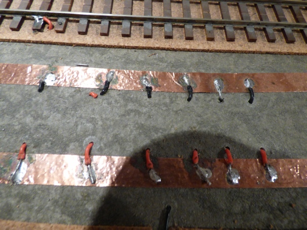
Brian introduced me to adhesive copper tape. We were able to fix this to the baseboard on both sides of every piece of track. We kept the rail closest to the centre of the layout black in an effort to reduce the risk of getting things wrong. Small holes were drilled adjacent to where power was needed. Track was cleaned using a fibre scratch brush before power supply wires were carefully solded to the track. ( When laying new track, the power supply wires are soldered to the underside of the track before fixing down.) The other end of this power side was soldered onto the copper strip. Each copper strip of the same colour was connected to another, within the same Power District.
At regular intervals we checked the validity of our work ensuring that there were NO shorts between black and red copper strips within each Power District.
TIP: Brian introduced a simple testing device that we now use when laying DCC power within a power district. This comprises a 2 AA batteries connected to a 12V buzzer. The idea is that connecting this circuit across the tracks whilst soldering droppers will buzz if a short circuit is detected. Has we had this at the beginning of laying DCC, we would have saved several man hours having to undo solder to find shorts discovered when we tested at the end of a days work.